
A PC Port is an interface or a point of connection or bridge between the pc and its peripherals. some of them are: mouse, keyboard, monitor or display units, printer, speaker, flash drive and so on.
The main purpose of a computer port is to act as linguist that helps computer to understand the peripherals, collect or transfer the data and etc.

A computer port is additionally referred to as Communication Port because it is responsible for communication between the PC and its peripherals. The female end of the connector is often referred as a port and it always is on the motherboard. In Computers, communication ports are divided into 2 kinds, depending on type or protocol used for communication. This are Serial Ports and Parallel Ports.
A serial port is an interface through which peripherals can be connected using a serial protocol which involves the transmission of data one bit at a time over a single communication line. The foremost common style of port may be a D-Subminiature or a D-sub connector that carry RS-232 signals.
A parallel interface, is an interface that provides communication between a laptop and its peripheral in parallel mode i.e. information is transferred in both directions, in and out using more than one communication channel.
Here I will try to cover and provide introduction to differing kinds of ports.
PS/2
PS/2 connector is developed by IBM for connecting mouse and keyboard. It was introduced with IBM’s Personal Systems/2 series of computers and hence the name PS/2 connector. PS/2 connectors are color coded as purple for keyboard and green for mouse.

PS/2 is a 6-pin DIN connector. The pin out diagram of a PS/2 female connector is shown below.

Even though the pin-out of mouse and keyboard on PS/2 ports are same, computers does not recognize the devise when connected to wrong port.
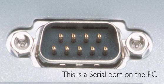
Serial Port
Even though the communication in PS/2 and USB is serial, technically, the term Serial Port is used to refer the interface that is compliant to RS-232 standard. There are two types of serial ports that are commonly found on a computer: DB-25 and DE-9.
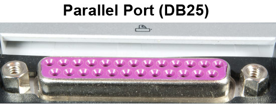
DB-25
DB-25 is a variant of D-sub connector and is the original port for RS-232 serial communication. They were developed as the main port for serial connections using RS-232 protocol but most of the applications did not require all the pins.
Hence, DE-9 was developed for RS-232 based serial communication while DB-25 was rarely used as a serial port and often used as a parallel printer port as a replacement of the Centronics Parallel 36 pin connector.
DE-9 or RS-232 or COM Port
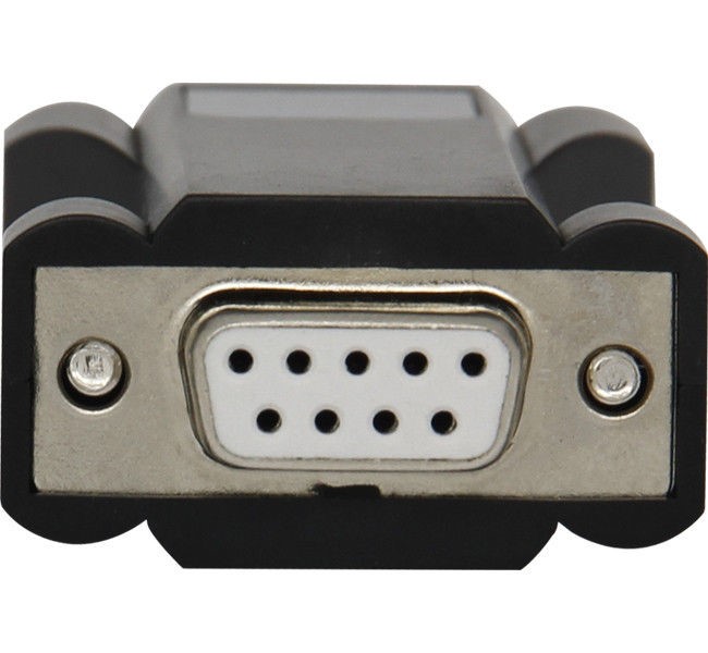
DE-9 is the main port for RS-232 serial communication. It is a D-sub connector with E shell and is often miscalled as DB-9. A DE-9 port is also called as a COM port and allows full duplex serial communication between the computer and it’s peripheral.
Some of the applications of DE-9 port are serial interface with mouse, keyboard, modem, uninterruptible power supplies (UPS) and other external RS-232 compatible devices
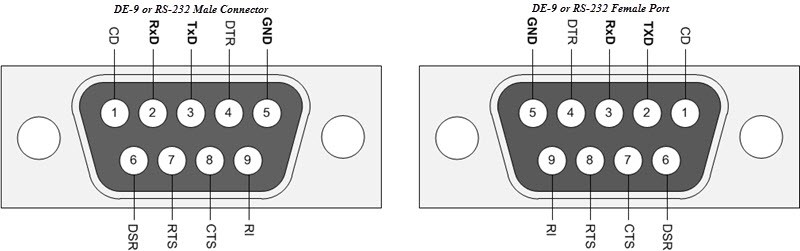
The pin-out diagram of DE-9 port is shown below
The use of DB-25 and DE-9 ports for communication is in decline and are replaced by USBs or other ports.
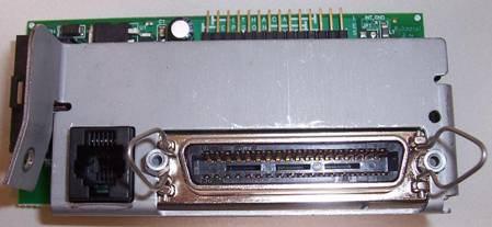
Parallel Port or Centronics 36 Pin Port
Parallel port is an interface between computer and peripheral devices like printers with parallel communication. The Centronics port is a 36 pin port that was developed as an interface for printers and scanners and hence a parallel port is also called as a Centronics port.
Before the wide use of USB ports, parallel ports are very common in printers. The Centronics port was later replaced by DB-25 port with parallel interface.
Audio Ports
Audio ports are used to connect speakers or other audio output devices with the computer. The audio signals can be either analogue or digital and depending on that the port and its corresponding connector differ.
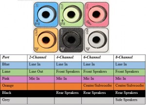
Surround Sound Connectors or 3.5 mm TRS Connector
It is the most commonly found audio port that can be used to connect stereo headphones or surround sound channels. A 6 connector system is included on majority of computers for audio out as well as a microphone connection.
The 6 connectors are color coded as Blue, Lime, Pink, Orange, Black and Grey. These 6 connectors can be used for a surround sound configuration of up to 8 channels
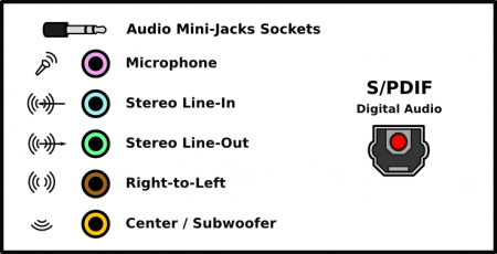
S/PDIF / TOSLINK
The Sony/Phillips Digital Interface Format (S/PDIF) is an audio interconnect used in home media. It supports digital audio and can be transmitted using a coaxial RCA Audio cable or an optical fiber TOSLINK connector.
Most computers home entertainment systems are equipped with S/PDIF over TOSLINK. TOSLINK (Toshiba Link) is most frequently used digital audio port that can support 7.1 channel surround sound with just one cable. In the following image, the port on the right is an S/PDIF port.
Video Ports
VGA Port
VGA port is found in many computers, projectors, video cards and High Definition TVs. It is a D-sub connector consisting of 15 pins in 3 rows. The connector is called as DE-15.
VGA port is the main interface between computers and older CRT monitors. Even the modern LCD and LED monitors support VGA ports but the picture quality is reduced. VGA carries analogue video signals up to a resolution of 648X480.
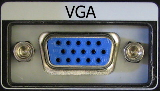
With the increase in use of digital video, VGA ports are gradually being replaced by HDMI and Display Ports. Some laptops are equipped with on-board VGA ports in order to connect to external monitors or projectors. The pin-out of a VGA port is shown below.

Digital Video Interface (DVI)
DVI is a high speed digital interface between a display controller like a computer and a display device like a monitor. It was developed with an aim of transmitting lossless digital video signals and replace the analogue VGA technology.
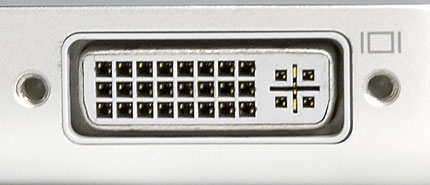
There are three types of DVI connectors based on the signals it can carry: DVI-I, DVI-D and DVI-A. DVI-I is a DVI port with integrated analogue and digital signals. DVI-D supports only digital signals and DVI-A supports only analogue signals.
The digital signals can be either single link or dual link where a single link supports a digital signal up to 1920X1080 resolution and a dual link supports a digital signal up to 2560X1600 resolution. The following image compares the structures of DVI-I, DVI-D and DVI-A types along with the pin-outs.
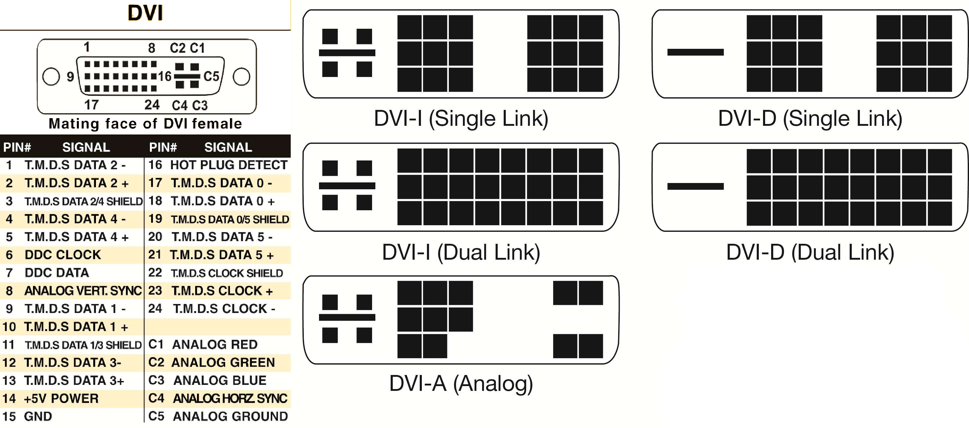
Mini-DVI
Mini – DVI port is developed by Apple as an alternative to Mini-VGA port and is physically similar to one. It is smaller than a regular DVI port.
It is a 32 pin port and is capable of transmitting DVI, composite, S-Video and VGA signals with respective adapters. The following image shows a Mini – DVI port and its compatible cable
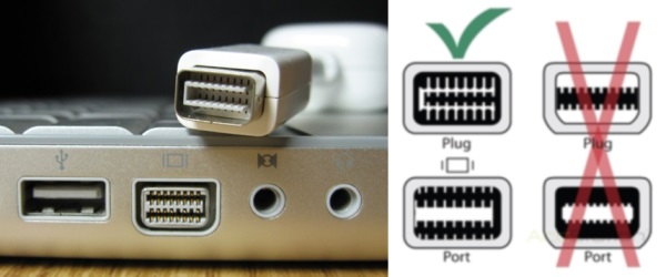
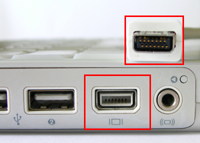
Micro – DVI
Micro – DVI port, as the name suggests is physically smaller than Mini – DVI and is capable of transmitting only digital signals.
This port can be connected to external devices with DVI and VGA interfaces and respective adapters are required. In the following image, a Micro – DVI port can be seen adjacent to headphone and USB ports.
Display Port
Display Port is a digital display interface with optional multiple channel audio and other forms of data. Display Port is developed with an aim of replacing VGA and DVI ports as the main interface between a computer and monitor.
The latest version Display-Port 1.3 can handle a resolution up to 7680 X 4320.
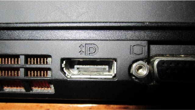
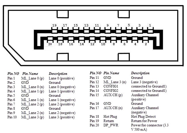
The Display Port has a 20 pin connector, which is a very less number when compared to DVI port and offers better resolution. The pin out diagram of a Display Port is shown below.
RCA Connector
RCA Connector can carry composite video and stereo audio signals over three cables. Composite video transmits analogue video signals and the connector is as yellow colored RCA connector.
The video signals are transmitted over a single channel along with the line and frame synchronization pulses at a maximum resolution of 576i (standard resolution).
The red and white connectors are used for stereo audio signals (red for right channel and white for left channel).
Component Video
Component Video is an interface where the video signals are split into more than two channels and the quality of the video signal is better that Composite video.
Like composite video, component video transmits only video signals and two separate connectors must be used for stereo audio. Component video port can transmit both analogue and digital video signals.
The ports of the commonly found Component video uses 3 connectors and are color coded as Green, Blue and Red.

S-Video
S-Video or Separate Video connector is used for transmitting only video signals. The picture quality is better than that of Composite video but has a lesser resolution than Component video.
The S-Video port is generally black in color and is present on all TVs and most computers. S-Video port looks like a PS/2 port but consists of only 4 pins.
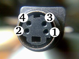
Out of the 4 pins, one pin is used to carry the intensity signals (black and white) and other pin is used to carry color signals. Both these pins have their respective ground pins. The pin-out diagram of an S-Video port is shown below.
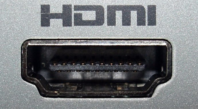
HDMI – High-Definition Multimedia Interface
HDMI is an abbreviation of High Definition Media Interface. HDMI is a digital interface to connect High Definition and Ultra High Definition devices like Computer monitors, HDTVs, Blu-Ray players, gaming consoles, High Definition Cameras etc.
HDMI can be used to carry uncompressed video and compressed or uncompressed audio signals. The HDMI port of type A is shown below.
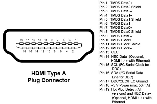
The HDMI connector consists of 19 pins and the latest version of HDMI i.e. HDMI 2.0 can carry digital video signal up to a resolution of 4096×2160 and 32 audio channels. The pinout diagram of an HDMI port is as follows.
Mini And micro HDMI ports
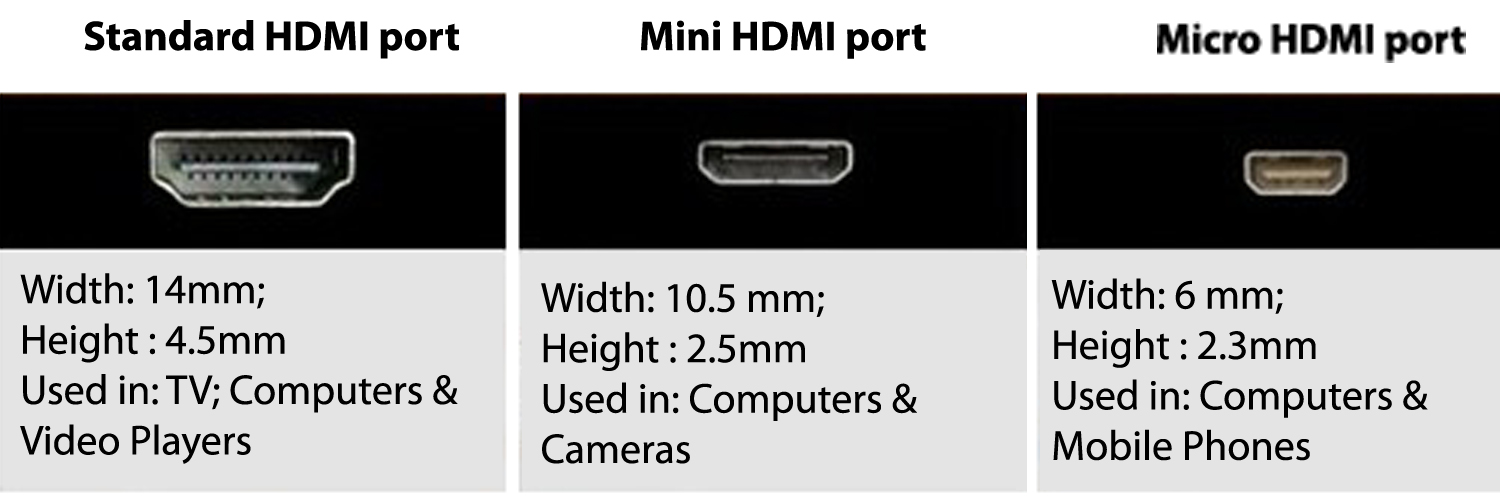
Mini HDMI is the next smallest connector and can be found on many new high definition camcorders and high resolution DSLR’s.
Micro HDMI is the smallest HDMI port for now. it’s supported on devices created by brands like HTC, Samsung and Motorola.
USB – Universal Serial Bus
USB replaced serial ports, parallel ports, PS/2 connectors, game ports and power chargers for portable devices.
USB port can be used to transfer data, act as an interface for peripherals and even act as power supply for devices connected to it. There are three kinds of USB ports: Type A, Type B or mini USB and Micro USB.
USB Type A
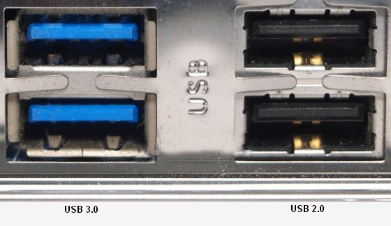
USB Type-A port is a 4 pin connector. There are different versions of Type – A USB ports: USB 1.1, USB 2.0 and USB 3.0. USB 3.0 is the common standard and supports a data rate of 400MBps.
USB 3.1 is also released and supports a data rate up to 10Gbps. The USB 2.0 is Black color coded and USB 3.0 is Blue. The following image shows USB 2.0 and USB 3.0 ports.
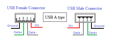
The pinout diagram of USB Type – A port is shown below. The pinout is common to all standards of Type – A.
USB-A: This kind of plug is most frequently seen on cables that are permanently attached to a device, such as one on a cable that connects a keyboard or mouse to the computer.
USB-B: Typically plugs into an upstream receptacle on a device that uses a removable cable, e.g. a printer.
Mini-A & Mini-B: Mini-A is now deprecated, but both these plugs are plugs are approximately 3 by 7 mm. These are used in PDAs, mobile phone and cameras.
Micro-B: Micro plugs have a similar width as the Minis but approximately half the thickness. These enable integration into thinner portable devices.
Micro-AB: This receptacle is capable of accepting either a Micro-A plug or a Micro-B plug
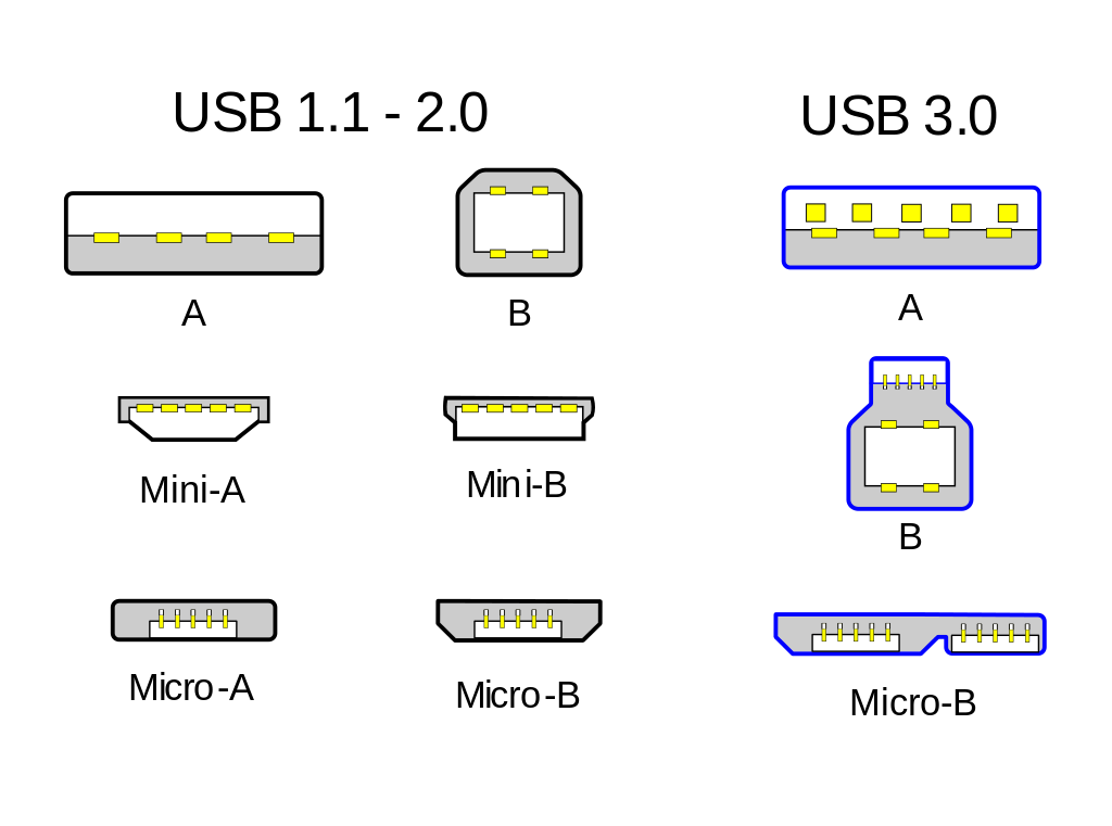
Speed rates are: USB 1.1 -12 Mb/s , USB 2.0 – 480 Mb/s, USB 3 – 5 Gb/s
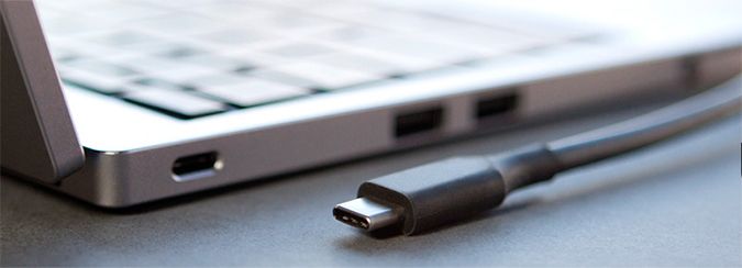
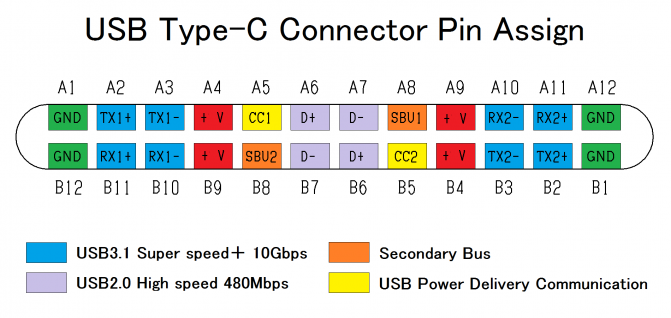
USB Type C
USB Type – C is the latest specification of the USB and is a reversible connector. USB Type – C is supposed to replace Types A and B and is considered future proof.
The port of USB Type – C consists of 24 pins. The pin-out diagram of USB Type – C is shown below. USB Type – C can handle a current of 3A.
This feature of handling high current is used in the latest Fast Charging Technology where a Smart Phone’s battery will reach its full charge is very less time.
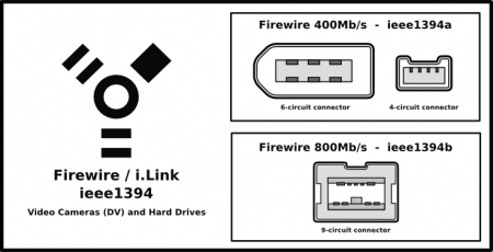
Firewire
Firewire 400MB/s: Can transfer data between devices at 100, 200, or 400 Mbit/s half-duplex data rates
Firewire 800Mb/s: Can transfer data at a rate of 786.432 Mbit/s full-duplex
RJ-45
Ethernet is a networking technology that is used to connect your computer to Internet and communicate with other computers or networking devices.
The interface that is used for computer networking and communications is known as Registered Jack (RJ) and RJ – 45 port in particular is used for Ethernet over cable. RJ-45 connector is an 8 pin – 8 contact (8P – 8C) type modular connector.
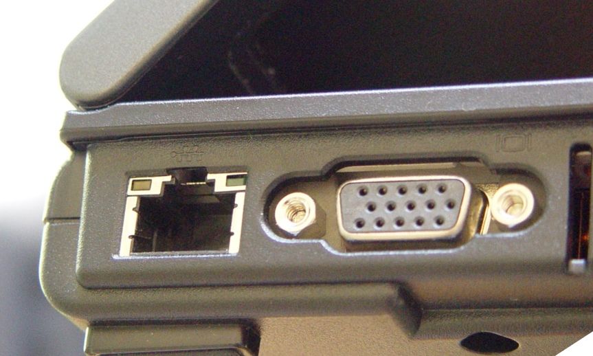
The latest Ethernet technology is called Gigabit Ethernet and supports a data transfer rate of over 10Gigabits per second. The Ethernet or a LAN port with 8P – 8C type connector along with the male RJ-45 cable is shown below.
The un – keyed 8P – 8C modular connector is generally referred to the Ethernet RJ-45. Often, RJ-45 ports are equipped with two LED s for indicating transmission and packet detection.
As mentioned earlier, an Ethernet RJ-45 port has 8 pins and the following picture depicts the pin-out of one.

RJ-11
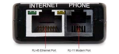
RJ-11 is another type of Registered Jack that is used as an interface for telephone, modem or ADSL connections. Even though computers are almost never equipped with an RJ-11 port, they are the main interface in all telecommunication networks.
RJ-45 and RJ11 ports look alike but RJ-11 is a smaller port and uses a 6 point – 4 contact (6P – 4C) connector even though a 6 point – 2 contact (6P – 2C) is sufficient. The following is a picture of an RJ-11 port and its compatible connector.
e-SATA
e-SATA is an external Serial AT Attachment connector that is used as an interface for connecting external mass storage devices. Modern e-SATA connector are called e-SATAp and stands for Power e-SATA ports.
They are hybrid ports capable of supporting both e-SATA and USB. Neither the SATA organization nor the USB organization has officially approved the e-SATAp port and must be used at user’s risk.
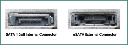
The above image is of an e-SATA port. It shows that both e-SATA and USB devices can be connected.
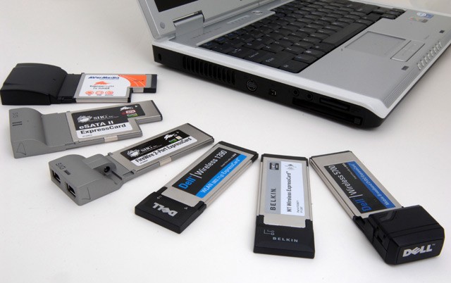
PCMCIA
Personal Computer Memory Card International Association (or, more commonly, PC Card) was used in a wide range of products (typically for laptops) such as WiFi, networking and flash memory. Other terms often associated with PCMCIA are Card Bus and its successor, Express Card; however, the PCMCIA Association was dissolved in 2009 and all Standards are now managed by the USB.
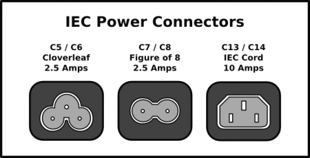
Power connectors
C5 / C6: “Cloverleaf” or “Mickey Mouse” power connectors can be seen on the majority of laptop power supplies and portable projectors
C7 / C8: C7 is also sometimes called “Shotgun.” These connectors can be found on cassette recorders, battery/mains operated radios, some full size AV equipment, laptop computer power supplies, video game consoles
C13/C14: C14 is used as an inlet to attach the power cord to the power supply, as do many monitors, printers and other peripherals. While many older computers also provide a panel-mounting C13 outlet for powering the monitor
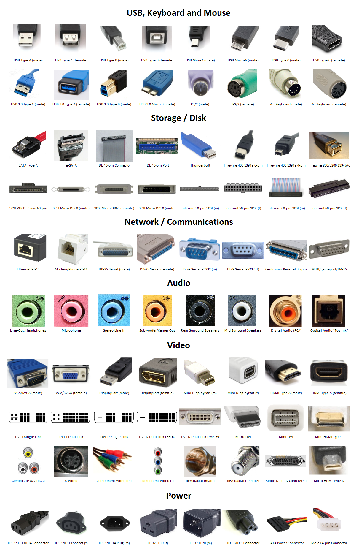
All the computer port and connectors

thank you for the image’s
LikeLike
Need to add anchor IDs the the H2 elements in the HTMLand add an index of links at the top of the page to reach each different connector types shown. PS/2 and links to them PS/2,… in the index.
LikeLike
Good Post
LikeLike